User Tools
Sidebar
Table of Contents
Benchmarks
This content has been moved to hubzero. LJ Hwang 2020.12.29
Benchmarks for the Magma Dynamics Demonstration Suite (MADDs).
An Introduction and Tutorial to the "McKenzie Equations" for Magma Migration
A new formulation for the equations of magma migration in viscous materials as originally derived by McKenzie is presented, as well as a set of well-understood special case problems that form a useful benchmark-suite for developing and testing new codes. 1_katz_2007.pdf
Running stgMADDs Benchmarks
The Magma Development team has finished the alpha release of the Magma Dynamics Demonstration Suite (MADDs). The initial code implements the zero porosity/no melting magma benchmark for mid-ocean ridge solid flows in 2D and 3D built on the Underworld framework. The purpose of this code is principally to validate accurate pressure solvers for Stokes flow in current CIG supported software. The stgMADDs source code is available in CIG's Mercurial Repository (geodynamics.org/hg).
Download and Install stgMADDs
For a first time download of the stgMADDs repository, do the following:
Create the topmost repository with:
hg clone http://geodynamics.org/hg/magma/3D/stgMADDs
Then obtain all the other repositories using:
./obtainRepositories.py
To push, you may have to use the ssh syntax, e.g.:
hg push ssh://hg@geodynamics.org/hg/magma/3D/stgMADDs
Caveat Emptor: This is very much an alpha release code for experimentation with the accuracy of different mixed FEM pressure solvers. Questions, complaints and bug reports should be directed to cig-magma@geodynamics.org.
Milestone 1 Results and Analysis
Details how to run the first milestone of the MADDs project in 2D and 3D and provides some results of these simulations. It also gives the rates of convergence of the pressure gradient solutions as the resolution is increased.
Running the code
In order to run the simulations for milestone 1 of the MADDs project (in 2D), first:
cd Magma/Models/Milestone1/Ridge2D_Quadratic
Then make a symbolic link to the executable binary (assuming the code has been successfully built):
ln -s ../../../../build/bin/StGermain .
The simulation may then be run (in parallel), passing in the respective XML file as input:
mpiexec -np <# of procs> ./StGermain Ridge2D.xml
Alternatively, the 3D simulation may be run as:
   cd Magma/Models/Milestone1/Ridge3D_Quadratic
   ln -s ../../../../build/bin/StGermain .
   mpiexec -np <# of procs.> ./StGermain Ridge3D.xml
Simulation results and error convergence
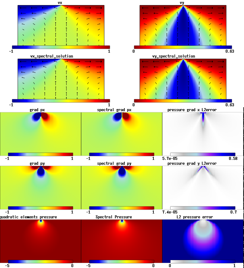
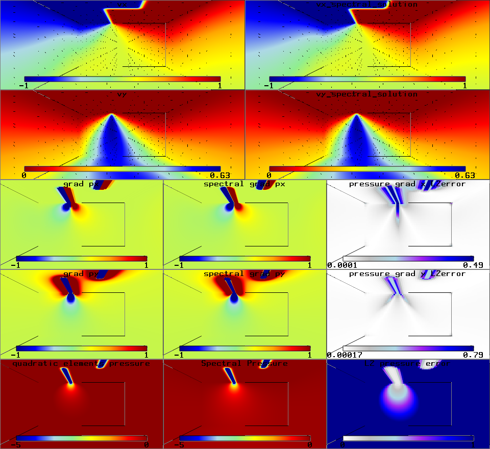
These simulations will produce graphical output of the velocity, pressure and pressure gradient solutions, as well as the analytic reference solutions and the element-wise normalised L2 error fields for the pressure and pressure gradients, as shown below. It will also generate text files to the output directory giving the node-wise results for the respective fields.
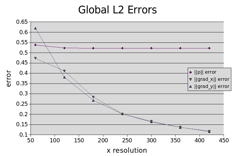
As the resolution is increased, the normalised global L2 errors are observed to decrease. This decrease is approximately linear for the 2D ridge model and slightly poorer for the 3D model. Graphs detailing the global errors as a function of resolution are given below.
2D Ridge Model
Velocity, pressure and pressure gradients solutions and L2 errors for a 2D ridge model with 120 x 60 elements.
 Global Pressure Gradient Errors for 2D Ridge Model. Normalised global L2 errors.
3D Ridge Model
Velocity, pressure and pressure gradient solutions and L2 error fields for 3D ridge model.
 Global Pressure Gradient Errors for 3D Ridge Model.
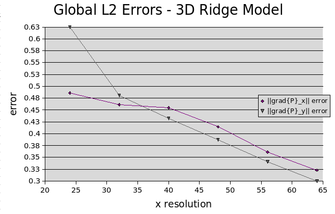 Global normalised L2 pressure gradient errors at varying resolutions.
Milestone 2 Results and Analysis
Details the results of the Milestone 2 simulations and analyzes the accuracy of the advection scheme.
Model descriptions
The second milestone contains several different models. In each a porosity distribution has been supplied, which acts as a force term on the stokes equation. The porosity is advected according to a semi Lagrangian scheme, with no natural diffusion. Details of these models are given below.
Simple Gaussian porosity field
The first model is a simple demonstration of how the porosity dependent force term drives the porosity distribution up through the domain. The domain is subjected to free slip boundary conditions, which also distort the porosity distribution as it is advected. This model is housed in the directory:
Magma/Models/Milestone2/ZPNM_SemiLagrangianPorosity/
with the XML file to be passed at run time being the Porridge.xml file.
Gaussian Porosity Field Advection. Advection of Gaussian porosity field as a Stokes equation force term. The lower density porosity region rises due to gravity.
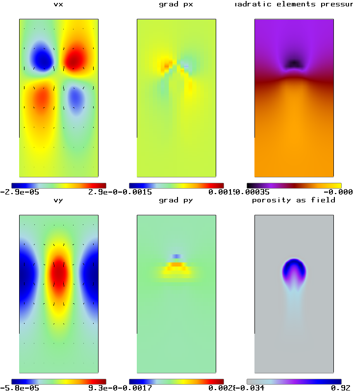
Ridge model with Gaussian porosity distribution
The second model is an extension of the first milestone, that is a ridge model with the initial boundary conditions loaded from a reference solution. However in this case a Gaussian porosity distribution has been added. The porosity distribution is distorted as it moves up through the domain in accordance with the velocity field generated from the boundary conditions. This model can be found in:
Magma/Models/Milestone2/RidgeModelWithGaussianPorosity/
with the XML file to be passed being Ridge2D.xml.
Ridge Model with Gaussian Porosity Field. Stokes flow with 2D ridge model boundary conditions and Gaussian porosity initial distribution, driven by a porosity dependent force term.
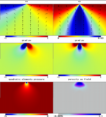
Validation of the advection scheme
As well as the models, a test is also supplied for validating the accuracy of the semi Lagrangian advection scheme. This involves an initial porosity distribution (either Gaussian or a diagonal line step function, as determined from the XML), which is subjected to a static shearing velocity field. The porosity distribution is subjected to the velocity field for a finite number of time steps (as determined from the XML input file), before the velocity field is reversed and the distribution advected back for the same number of time steps. The normalised global L2 error between the initial and final distributions is then calculated. This test is housed in the directory:
Magma/Models/Milestone2/tests/
And may be run using the input file testSemiLagrangianAdvection.xml.
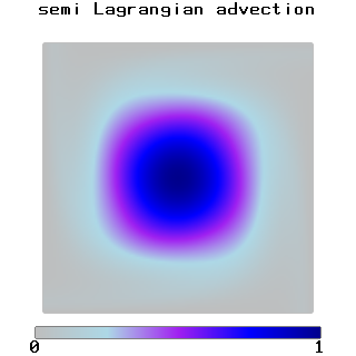
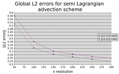
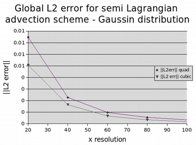
Running this simulation at varying resolutions, the convergence of the errors for the advection scheme were determined using both the Gaussian distribution and diagonal step function as initial conditions. The errors were recorded for schemes which used a cubic method as well as a quadratic method based on the element shape functions for interpolating the value at the end point of the characteristic. As can be observed from the convergence errors plots below, the quadratic and cubic interpolation method schemes converged at comparable (less than linear) rates using the step function initial condition, with an improvement in those results obtained using the cubic interpolation method. When the Gaussian initial distribution was applied (which was easier to solve accurately on account of the smoother gradients involved), both interpolation methods converged at a rate much better than linear, with the cubic interpolation method proving far superior to the quadratic method.
Semi Lagrangian Advection Scheme Test - Step Function.
Diagonal step function initial distribution subjected to a shearing velocity field.
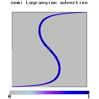 Semi Lagrangian Advection Scheme Test - Gaussian Distribution.
Gaussian initial distribution subjected to a shearing velocity field.
 Error Convergence for Advection Scheme - Step Function IC.
Normalised global L2 errors for semi Lagrangian advection scheme with a diagonal step function initial condition as a function of resolution.
Error Convergence for Advection Scheme - Gaussian IC.
Normalised global L2 errors for semi Lagrangian advection scheme with Gaussian initial distribution as a function of resolution.
Milestone 3 Results
Details the results for the third milestone, in which the melt velocity was determined given the existing solid velocity and pressure fields.
Model descriptions
Two different models were implemented for which the melt velocity was determined. The first of these was an extension of the ridge model implemented in Milestone 1, but with a constant porosity field, such that the solution was static in time. This model can be found in:
/Magma/Models/Milestone3/Ridge2D_FieldBasedConstantPorosity
The second model was an extension of the porosity driven Stokes flow with a Gaussian initial distribution implemented in milestone 2. This model resides at:
/Magma/Models/Milestone3/FieldBasedPorosityDrivenFlow2D
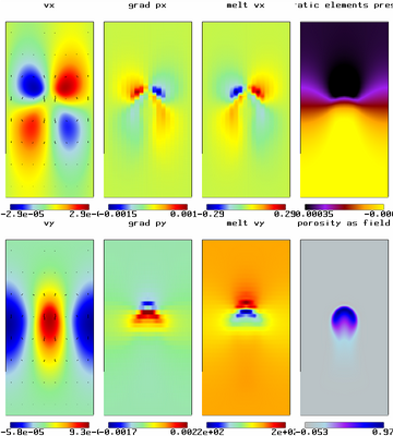
Since the melt velocity is decoupled from the McKenzie equations, it is relatively simple to calculate, provided that the pressure and solid velocity fields have already been accurately determined. As such no tests were applied to validate its accuracy, however qualitatively their behavior is observed to be correct.
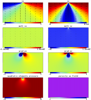
Melt Model - 2D Ridge with Constant Porosity.
Solid and melt velocity, pressure and pressure gradient fields for 2D ridge model with constant porosity. Melt velocity magnitudes are significantly larger near the point of discontinuity due to their proportionality to the pressure gradients, which are largest at these points.
 Melt Model - Gaussian Porosity Driven Flow
Solid and melt velocity, pressure and pressure gradient fields for Stokes flow driven by a Gaussian initial porosity distribution.
Milestone 4 Results and Analysis
Discussion of the system being modeled, and details of how to run the model with different initial conditions in 2 and 3D.
Problem Description
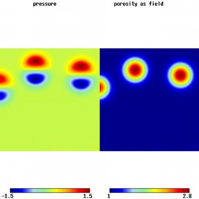
This milestone solves a porosity pressure system which involves the coupling of a Darcy flow to describe the compressibility of the permeable solid matrix and a time dependent advection equation for the porosity field. Together these equations allow for non-linear dispersive porosity waves. Given an initial porosity distribution which is itself a porosity wave, this wave should advect at a speed determined by the amplitude and the power used to determine the permeability from the porosity (as well as the velocity of the background solid), without any diffusion. If the initial porosity distribution is not itself a solitary porosity wave, with time these should emerge from the porosity field.
Running the Simulations
In order to run the solitary waves model, (int 2D) first:
cd Magma/Models/Milestone4/SolitaryWaves2D
Then make a symbolic link to the executable binary as:
ln -s ../../../../build/bin/StGermain .
The simulation may then be run in parallel as:
mpirun -np <# of procs> ./StGermain SolitaryWaves.xml
This will run the code with the default initial porosity distribution of a solitary wave with a wave speed of 7 and a porosity exponent of 3. The backgound solid velocity has been set in the file VelocityField.xml as -2, such that the wave should rise with a speed of 5. In order to verify that the wave is advecting at the correct speed, this may be changed to -7, which should then show the wave to be stationary.
An alternative initial porosity distribution of a vertically changing noisy 1D solitary wave may be set from the file sWaveSetup.xml by modifying the referenceSolutionFileName parameter to ./input/solitaryWaves1DGlobal.dat. This should then show a set of 2D solitary porosity waves emerging from the 1D distribution with time.
A 3D model may also be run by changing directories to:
cd Magma/Models/Milestone4/SolitaryWaves3D
and then repeating the procedures detailed above for the 2D system. The initial condition, read in from the file ./input/solitaryWaves3DGlobal.dat, is that of a single 1D solitary wave in the vertical direction set against a noisy background distribution which evolves with time into a set of 3D solitary waves.
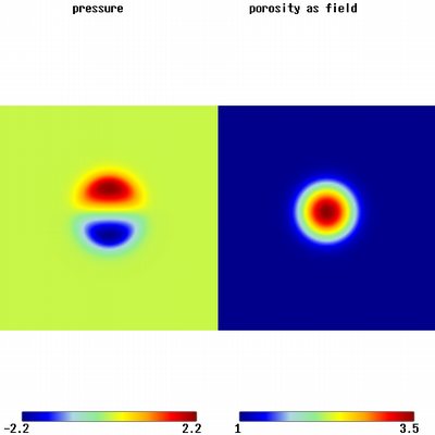
2D Solitary Wave.
A 2D solitary wave with a wave speed of 7 rising through a solid with a constant speed of -2. The wave shows no visible diffusive behavior.
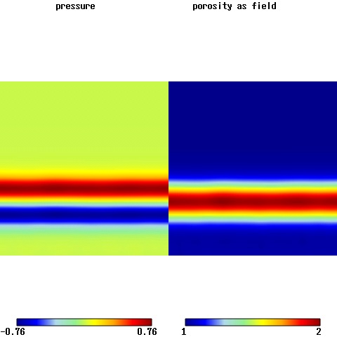
 Noisy 1D Solitary Wave Initial Condition.
Initial condition of a vertically changing 1D solitary wave with a certain amount of introduced noise, which allows 2D solitary waves to emerge over time.
 Emerging 2D Solitary Waves.
Solitary waves emerging from a noisy 1D solitary wave initial condition.
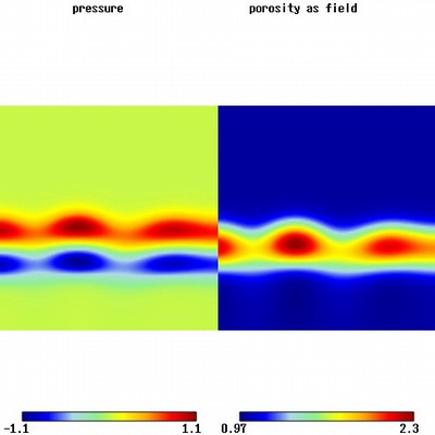 Emergent 2D Solitary Waves.
Solitary waves having emerged from a noisy 1D solitary wave initial distribution.
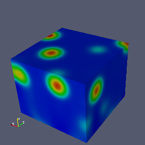 Emergent 3D Solitary Waves.
3D Solitary Waves emerging from a noisy 1D Solitary Wave initial distribution
Milestone 5 Results and Analysis
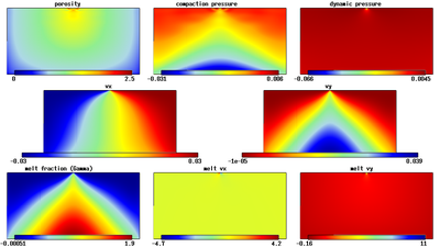
Results and analysis for the isoviscous McKenzie equations (with melting) driven by a corner flow velocity BC.
Problem Description
This model describes the full isoviscous McKenzie equations (with melting), for a system driven by a corner flow velocity boundary condition for the solid phase. These equations couple a Stokes system for the solid phase with a Darcy flow for the melt moving through the permeable solid, and an advection term for the porosity field. The flow is driven by a corner flow boundary condition for the solid, which creates a region of low dynamic pressure about the area of discontinuity, and a linear ramp in the melting function.
Running the Simulation
The model is run from the directory:
Magma/Models/Milestone5/IsoviscousMcKenzieRidge2D/
and executing as:
./StGermain IsoviscousMcKenzieRidge2D.xml
taking care to create a soft link to the StGermain binary in the build directory as before.
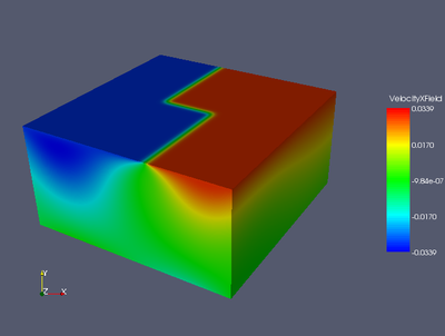
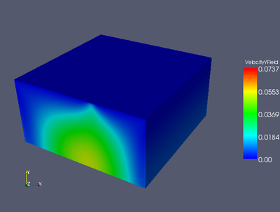
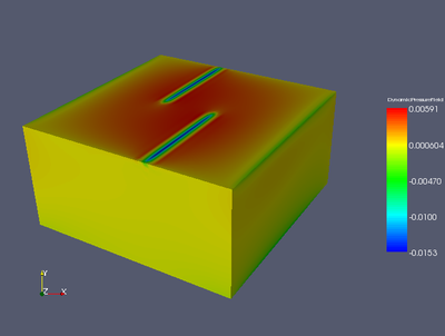
3D Model with Ridge Velocity Boundary Conditions A 3D model was also implemented, which is driven by Dirichlet BCs on the velocity field, which are interpolated onto the prescribed domain from an input file (the same one as for Milestone 1). The directory and execution command for running this model are given as:
  Magma/Models/Milestone5/IsoviscousMcKenzieRidge3D/
  ./StGermain IsoviscousMcKenzieRidge3D.xml
Some images for the x and y velocity components, the dynamic and compaction pressures, the porosity, the melt fraction and the x and y melt velocity components are attached below.
Isoviscous McKenzie System with Corner Flow BC - 1.
After 1 time step
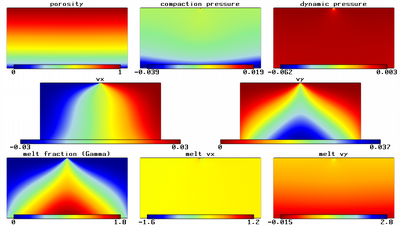 Isoviscous McKenzie System with Corner Flow BC - 50.
After 50 time steps
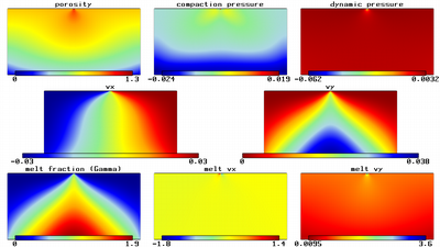 Isoviscous McKenzie System with Corner Flow BC - 3200.
After 3200 time steps.
 Velocity - x component.
x component of the velocity field for the 3D isoviscous McKenzie model with ridge BCs at time step 150.
 Velocity - y component.
y component of the velocity field for the 3D isoviscous McKenzie model with ridge BCs at time step 150.
 Dynamic (Stokes) pressure,
Dynamic pressure due to viscous shear for the 3D isoviscous McKenzie model with ridge BCs at time step 150.
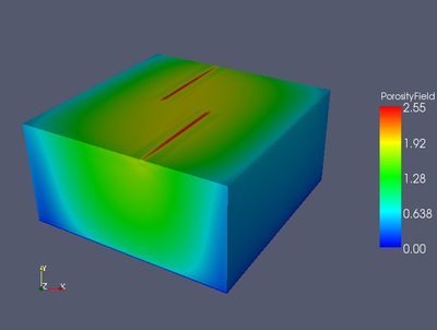
 Porosity.
Porosity field for the 3D isoviscous McKenzie model with ridge BCs at time step 150.
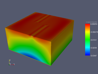
 Compaction pressure.
Compaction pressure due to compressibility of the solid phase for the 3D isoviscous McKenzie model with ridge BCs at time step 150.
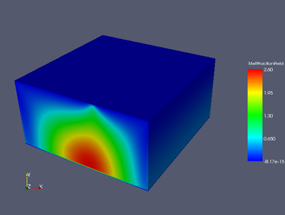
 Melt fraction.
Melt fraction field representing the melt to solid phase of the 3D isoviscous McKenzie model with ridge BCs at time step 150.
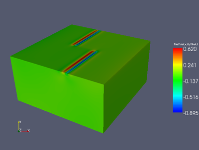
 Melt velocity - x component.
x component of the melt velocity field for the 3D isoviscous McKenzie model with ridge BCs at time step 150.
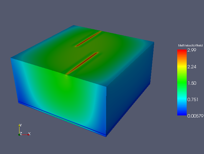
 Melt velocity - y component.
y component of the Melt velocity field for the 3D isoviscous McKenzie model with ridge BCs at time step 150.
